Pulse-code modulation (PCM) is a method used to digitally represent sampled analog signals. It is the standard form of digital audio in computers, Compact Discs, digital telephony and other digital audio applications. In a PCM stream, the amplitude of the analog signal is sampled regularly at uniform intervals, and each sample is quantized to the nearest value within a range of digital steps.
Linear pulse-code modulation (LPCM) is a specific type of PCM where the quantization levels are linearly uniform.[5] This is in contrast to PCM encodings where quantization levels vary as a function of amplitude (as with the A-law algorithm or the μ-law algorithm). Though PCM is a more general term, it is often used to describe data encoded as LPCM.
A PCM stream has two basic properties that determine the stream's fidelity to the original analog signal: the sampling rate, which is the number of times per second that samples are taken; and the bit depth, which determines the number of possible digital values that can be used to represent each sample.
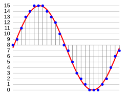 In the diagram, a sine wave
(red curve) is sampled and quantized for PCM. The sine wave is sampled
at regular intervals, shown as vertical lines. For each sample, one of
the available values (on the y-axis) is chosen by some algorithm. This
produces a fully discrete representation of the input signal (blue
points) that can be easily encoded as digital data for storage or
manipulation. For the sine wave example at right, we can verify that the
quantized values at the sampling moments are 8, 9, 11, 13, 14, 15, 15,
15, 14, etc. Encoding these values as binary numbers would result in the following set of nibbles: 1000 (23×1+22×0+21×0+20×0=8+0+0+0=8),
1001, 1011, 1101, 1110, 1111, 1111, 1111, 1110, etc. These digital
values could then be further processed or analyzed by a digital signal processor. Several PCM streams could also be multiplexed into a larger aggregate data stream, generally for transmission of multiple streams over a single physical link. One technique is called time-division multiplexing (TDM) and is widely used, notably in the modern public telephone system.
In the diagram, a sine wave
(red curve) is sampled and quantized for PCM. The sine wave is sampled
at regular intervals, shown as vertical lines. For each sample, one of
the available values (on the y-axis) is chosen by some algorithm. This
produces a fully discrete representation of the input signal (blue
points) that can be easily encoded as digital data for storage or
manipulation. For the sine wave example at right, we can verify that the
quantized values at the sampling moments are 8, 9, 11, 13, 14, 15, 15,
15, 14, etc. Encoding these values as binary numbers would result in the following set of nibbles: 1000 (23×1+22×0+21×0+20×0=8+0+0+0=8),
1001, 1011, 1101, 1110, 1111, 1111, 1111, 1110, etc. These digital
values could then be further processed or analyzed by a digital signal processor. Several PCM streams could also be multiplexed into a larger aggregate data stream, generally for transmission of multiple streams over a single physical link. One technique is called time-division multiplexing (TDM) and is widely used, notably in the modern public telephone system.
The PCM process is commonly implemented on a single integrated circuit generally referred to as an analog-to-digital converter (ADC).
 ).[note 1] The sampling theorem
shows PCM devices can operate without introducing distortions within
their designed frequency bands if they provide a sampling frequency
twice that of the input signal. For example, in telephony, the usable voice frequency band ranges from approximately 300 Hz to 3400 Hz. Therefore, per the Nyquist–Shannon sampling theorem,
the sampling frequency (8 kHz) must be at least twice the voice
frequency (4 kHz) for effective reconstruction of the voice signal.
).[note 1] The sampling theorem
shows PCM devices can operate without introducing distortions within
their designed frequency bands if they provide a sampling frequency
twice that of the input signal. For example, in telephony, the usable voice frequency band ranges from approximately 300 Hz to 3400 Hz. Therefore, per the Nyquist–Shannon sampling theorem,
the sampling frequency (8 kHz) must be at least twice the voice
frequency (4 kHz) for effective reconstruction of the voice signal.
The electronics involved in producing an accurate analog signal from the discrete data are similar to those used for generating the digital signal. These devices are Digital-to-analog converters (DACs). They produce a voltage or current (depending on type) that represents the value presented on their digital inputs. This output would then generally be filtered and amplified for use.
Linear pulse-code modulation (LPCM) is a specific type of PCM where the quantization levels are linearly uniform.[5] This is in contrast to PCM encodings where quantization levels vary as a function of amplitude (as with the A-law algorithm or the μ-law algorithm). Though PCM is a more general term, it is often used to describe data encoded as LPCM.
A PCM stream has two basic properties that determine the stream's fidelity to the original analog signal: the sampling rate, which is the number of times per second that samples are taken; and the bit depth, which determines the number of possible digital values that can be used to represent each sample.
Modulation

Sampling and quantization of a signal (red) for 4-bit PCM
The PCM process is commonly implemented on a single integrated circuit generally referred to as an analog-to-digital converter (ADC).
Demodulation
To recover the original signal from the sampled data, a "demodulator" can apply the procedure of modulation in reverse. After each sampling period, the demodulator reads the next value and shifts the output signal to the new value. As a result of these transitions, the signal has a significant amount of high-frequency energy caused by aliasing. To remove these undesirable frequencies and leave the original signal, the demodulator passes the signal through analog filters that suppress energy outside the expected frequency range (greater than the Nyquist frequency).[note 1] The sampling theorem
shows PCM devices can operate without introducing distortions within
their designed frequency bands if they provide a sampling frequency
twice that of the input signal. For example, in telephony, the usable voice frequency band ranges from approximately 300 Hz to 3400 Hz. Therefore, per the Nyquist–Shannon sampling theorem,
the sampling frequency (8 kHz) must be at least twice the voice
frequency (4 kHz) for effective reconstruction of the voice signal.The electronics involved in producing an accurate analog signal from the discrete data are similar to those used for generating the digital signal. These devices are Digital-to-analog converters (DACs). They produce a voltage or current (depending on type) that represents the value presented on their digital inputs. This output would then generally be filtered and amplified for use.
No comments:
Post a Comment